
CYPECAD, CYPE 3D and the Portal frame generator generate detailed ultimate limit state (U.L.S.) check reports. The U.L.S. reports contain all the checks these programs carry out to design concrete, steel, aluminium and timber elements. Each check refers to the design code and article requiring the check, or the criteria which has been applied to carry it out. The detailed contents of the U.L.S. reports makes these essential documents with which users can verify, justify and optimise the design of the structural elements that have been analysed.
The programs and structural elements for which these reports are generated can be consulted in the CYPE programs which generate U.L.S. check reports section.
Use of the Ultimate limit state check reports
The U.L.S. reports contain all the checks carried out by the program to design and analyse concrete, steel, aluminium and timber elements. Therefore, they constitute an important document with which users can:
- Verify and justify the design of the analysed elements. Users can examine, each of the checks carried out by the program to design and analyse the reinforced concrete, steel, aluminium and timber sections.
- Optimise the design of the analysed elements. By observing the checks that fail, it is easier to decide on the optimum solution to solve the problem (increase sections or reinforcement, provide stiffeners, check whether the introduced buckling coefficients are adequate...). Similarly, if all the checks are met, these reports also contribute on deciding how to obtain a better usage coefficient.
The level of detail of these reports also acts as a guide allowing users to know all the checks to which the analysed structural element is submitted to. The program does not simply indicate whether the check fails or not, it also indicates which specific checks are not complied with. Additionally, each check refers to the design code and article requiring it.
CYPE programs which generate U.L.S. check reports
CYPECAD (including its integrated 3D structures), CYPE 3D and the Portal frame generator generate detailed ultimate limit state check reports. Below are the elements and materials for which these programs generate the U.L.S. reports.
CYPECAD generates ultimate limit state reports for the following elements:
- Reinforced concrete and steel columns
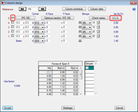
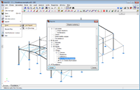
The U.L.S. reports for reinforced concrete and steel (rolled, welded and cold-formed) columns are obtained from CYPECAD’s Column reinforcement editor (Results > Columns/Shear walls > Edit > select column).
The Edit option displays the new column reinforcement editor. Within this editor, the U.L.S. reports are generated by selecting the ( ) symbol from the “Combination summary” table (to generate the U.L.S. report of the span of the selected column), or by pressing the (
 ) button (to generate the U.L.S. report of all the spans of the selected column). The new column editor is available when the job is analysed with the following concrete codes:
- ABNT NBR 6118:2007 (Brazil)
- ACI 318M-08 (USA – International)
- B.A.E.L 91 (France)
- CIRSOC 201:2005 (Argentina)
- EHE-08 (Spain)
- Eurocode 2 (EU International)
- Eurocode 2 (France)
- Eurocode 2 (Portugal)
- IS 456:2000 (India)
- NBR 6118:2007 (Brazil)
- NCh430.Of2008 (Chile)
- NSR-10 (Colombia) (Título C - Concreto estructural)
- NTC: 14-01-2008 (Italy)
- NTE E.060:2009 (Peru)
 If a different concrete code is selected, the current version of CYPECAD does not yet generate the U.L.S. reports for concrete columns (other concrete codes will be implemented in the near future). It does, however, generate the U.L.S. reports for steel columns (for the majority of steel codes which are implemented in the program). In this case, the Edit option displays the classic column reinforcement editor, where the (
 ) button can be selected for a steel column span (rolled, welded or cold-formed).
- Rolled, welded and cold-formed steel beams
As is the case with steel columns, the U.L.S. reports for rolled, welded and cold-formed steel beams are available for the majority of steel design codes which are implemented in the program. These reports can be obtained using the following options: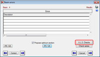
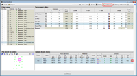
- Steel beams
Results > Beams/Walls > Beam errors > Select steel beam > U.L.S. Checks button. - Sloped steel beams
Results > Beams/Walls > Sloped beams > U.L.S. Checks > Select steel beam.
- Steel beams
- Steel (rolled, welded and cold-formed), aluminium and timber bars of CYPECAD’s integrated 3D structures
Since CYPECAD’s integrated 3D structures work the same way as CYPE 3D, please consult the section on CYPE 3D to know how the U.L.S. reports are obtained for these structural elements.
CYPECAD also generates a summarised U.L.S. check report for concrete columns –only for the design codes which generate detailed U.L.S. check reports, steel columns and horizontal and sloped steel beams (this summary does not include bars belonging to any integrated 3D structures which may exist). To generate this summary, select the option File > Print > Job reports > U.L.S. checks for columns and beams button.
CYPE 3D and CYPECAD’s integrated 3D structures generate detailed ultimate limit state check reports for steel (rolled, welded and cold-formed), aluminium and timber bars, which have been designed with the majority of the codes implemented in the program. The bar sections for which the U.L.S. reports can be obtained are:
- Any section of a bar indicated by the user
Analysis > U.L.S. Checks > At the indicated point. - The critical sections in each check of a bar selected by the user
Analyse > U.L.S. Checks > At the worst point. - The critical sections in each check of ten bars with errors or with the highest usage coefficient
File > Print > Job report > Activate Structure – Results – Bars – U.L.S. Checks (Complete). - The critical sections in each check of all the bars of the structure (summarised report)
File > Print > Job report > Activate Structure – Results – Bars – U.L.S. Checks (Summarised).
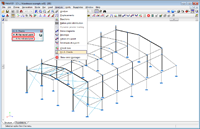
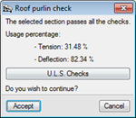 Portal frame generator generates detailed ultimate limit state reports for the purlins which have been designed. To visualise and print these reports, click on the U.L.S. Checks button, which is available in the dialogue box: Job data > Lateral and roof purlin edition > select Purlins on roof or Purlins on sides > Accept.
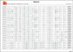
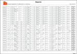
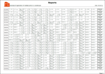
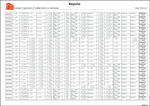
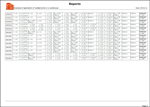
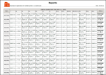
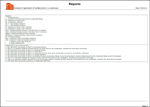
Examples of ultimate limit state check reports
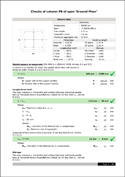
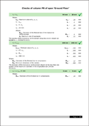
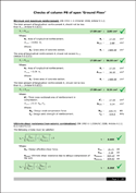
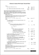
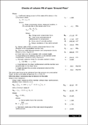
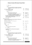
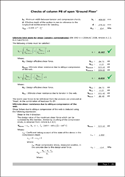
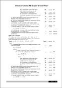
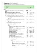
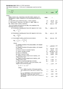
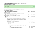
U.L.S. check report of a reinforced concrete column. CYPECAD
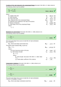
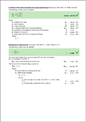
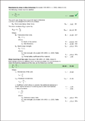
U.L.S. check report of a beam of a dual pitch frame. CYPE 3D
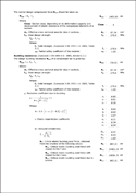
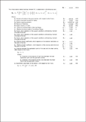
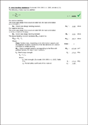
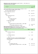
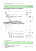
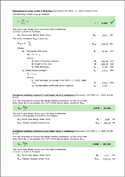
U.L.S. check report of a column of a dual pitch frame. CYPE 3D
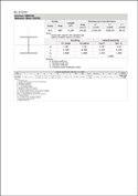
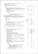
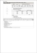
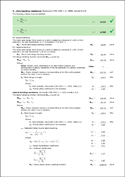
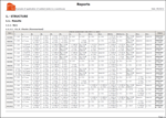
Summarised U.L.S. check report of all the bars of the structure. CYPE 3D
CYPE 3D modules:
CYPECAD modules:
- Steel columns
- Steel beams
- Joist floor slabs (generic concrete joists)
- Joist floor slabs (in-situ, precast and steel)
- Timber joist floor slabs
- Waffle slabs
- Flat slabs
- Punching shear verification (Also operates as an independent program)
- Composite slabs
- Hollow core slabs
- Post-tensioned concrete slabs for buildings
- Shear walls
- Reinforced concrete walls
- Plane stress walls
- Stairs
- Mat foundations and foundation beams
- Concrete block walls
- Interaction of the structure with the construction elements
- Automatic job introduction: DXF, DWG and CAD/BIM models
- Collective protection systems
Modules common to CYPECAD and CYPE 3D:
- Concrete columns
- Composite steel and concrete columns
- Concrete beams
- Timber sections
- Pile caps (includes strap and tie beams)
- Baseplates
- Footings (pad and strip) (includes strap and tie beams)
- Advanced design of surface foundations
- Fire resistance check
- Parallel analysis with two multiprocessors
- Parallel analysis with up to eight processors
- Joints I. Welded. Warehouses with rolled and welded steel I sections
- Joints II. Bolted. Warehouses with rolled and welded steel I sections
- Joints III. Welded. Building frames with rolled and welded steel I sections
- Joints IV. Bolted. Building frames with rolled and welded steel I sections
- Joints V. Flat trusses with hollow structural sections
- Export to Tekla
Tel. USA (+1) 202 569 8902 // UK (+44) 20 3608 1448 // Spain (+34) 965 922 550 - Fax (+34) 965 124 950